Mission Planning
How To Plan A Photogrammetry Mission
Plan a mapping mission from the deliverable backward. This guide covers deliverable-first thinking, route geometry, margins, heading choices, corridor examples, and the preflight checks that keep the job physically executable.
Key Takeaways
- A photogrammetry mission should start from the deliverable, then flow into GSD, overlap, sensor choice, and route geometry.
- Polygon shape, outward margin, and heading matter as much as camera math when you are trying to build an efficient route.
- A plan is incomplete until battery life, weather, lighting, hardware limits, and launch conditions are all checked against the route.
Reverse-Engineer The Deliverable
Professional mission planning begins with the output, not the aircraft. If you do not know what the final deliverable must support, you are not planning a photogrammetry mission yet; you are only scheduling a flight.
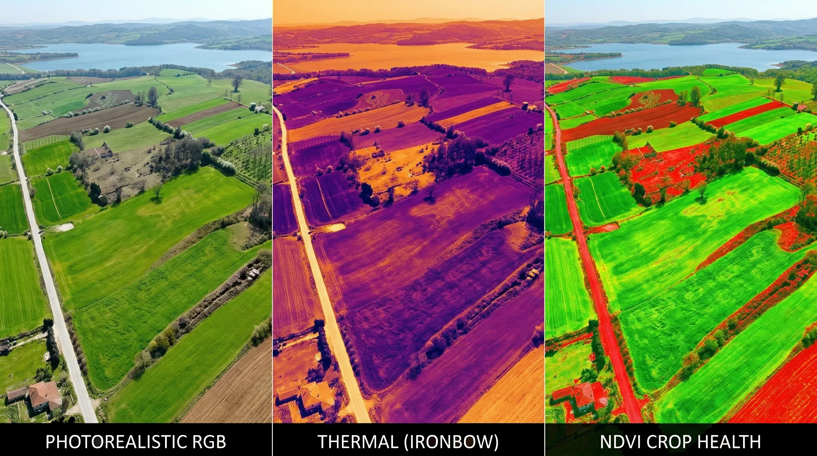
The question comes first: do you need a broad orthomosaic, a measurement-grade model, a thermal inspection pass, or multispectral analysis? Each one demands different tolerances, different sensors, and different trade-offs.
- Measurement work benefits from mapping-grade RGB payloads and careful geometric stability.
- Thermal inspection pushes altitude lower and overlap higher because the native resolution is usually much lower.
- Multispectral missions care deeply about radiometric consistency, calibration, and timing around solar conditions.
Physics Of Geometry And Flight Planning
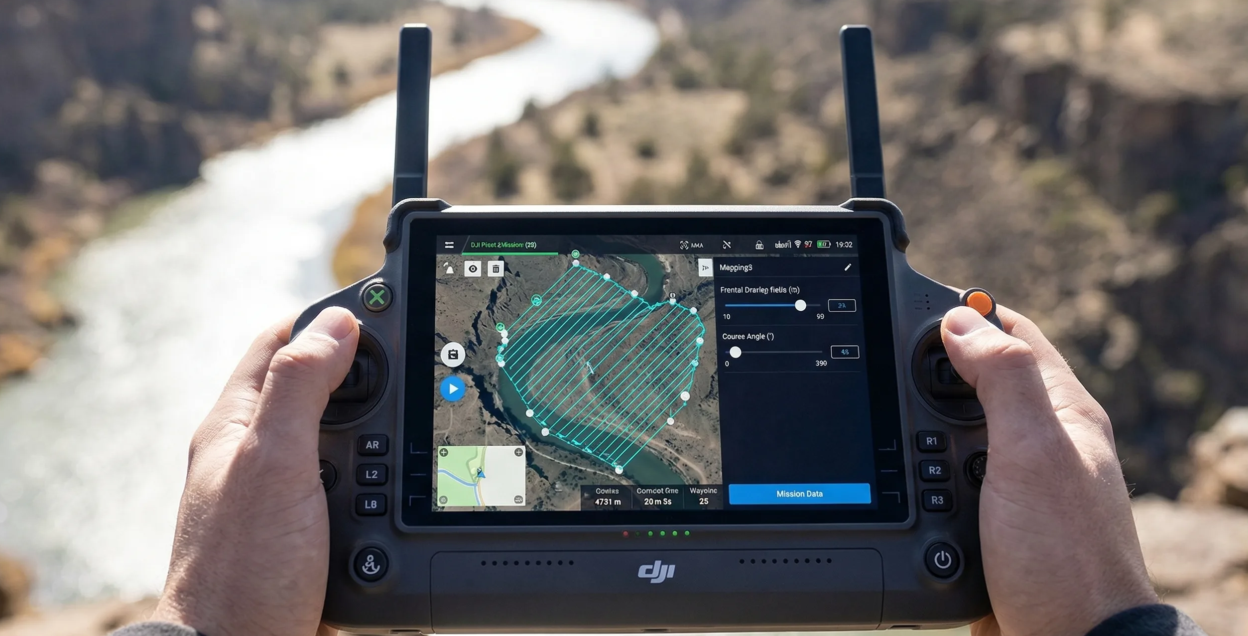
Once the deliverable is known, the site geometry takes over. Route efficiency depends on the shape of the survey area, the chosen heading, and the amount of outward margin. Default planner algorithms are strongest on simple open polygons and much weaker on corridors, concave boundaries, and pinch points.
This is why route visualization is non-negotiable. A clean-looking automatic plan on a rectangle can become wasteful and battery-heavy when the same logic is forced across a narrow corridor or an irregular construction boundary.
If the software keeps drawing strips across the short axis of a long site, the aircraft may spend more energy making turns outside the useful area than collecting productive imagery.

Importance Of Outward Margin
The edge of a flight block is always weaker than the middle because it has less geometric redundancy. At the outer limit of the route, the photogrammetry engine has fewer intersecting rays and fewer opportunities to stabilize the surface.
That is where bowl effect and edge weakness start to show up. Outward margin is the practical answer: extend the route beyond the target area so the actual deliverable sits inside the stronger center of the image block rather than right on the weakest line.
Heading, Strip Density, And Aerodynamics
Heading is not just a cosmetic route setting. Terrain orientation, wind direction, and corridor shape all change how stable the aircraft will be in flight and how efficiently strips fit the site.
A strong crosswind can force the aircraft into a large crab angle, increase yaw corrections, and raise the odds of vibration or landing gear intrusion. Manual heading often becomes the better choice on irregular sites because it lets you line the route up with the corridor and the prevailing wind instead of fighting both.
Strip density should be evaluated at the same time. A tighter route may improve overlap, but it also increases turns, data volume, and battery drain. The right heading is usually the one that preserves coverage quality while minimizing waste outside the useful footprint.
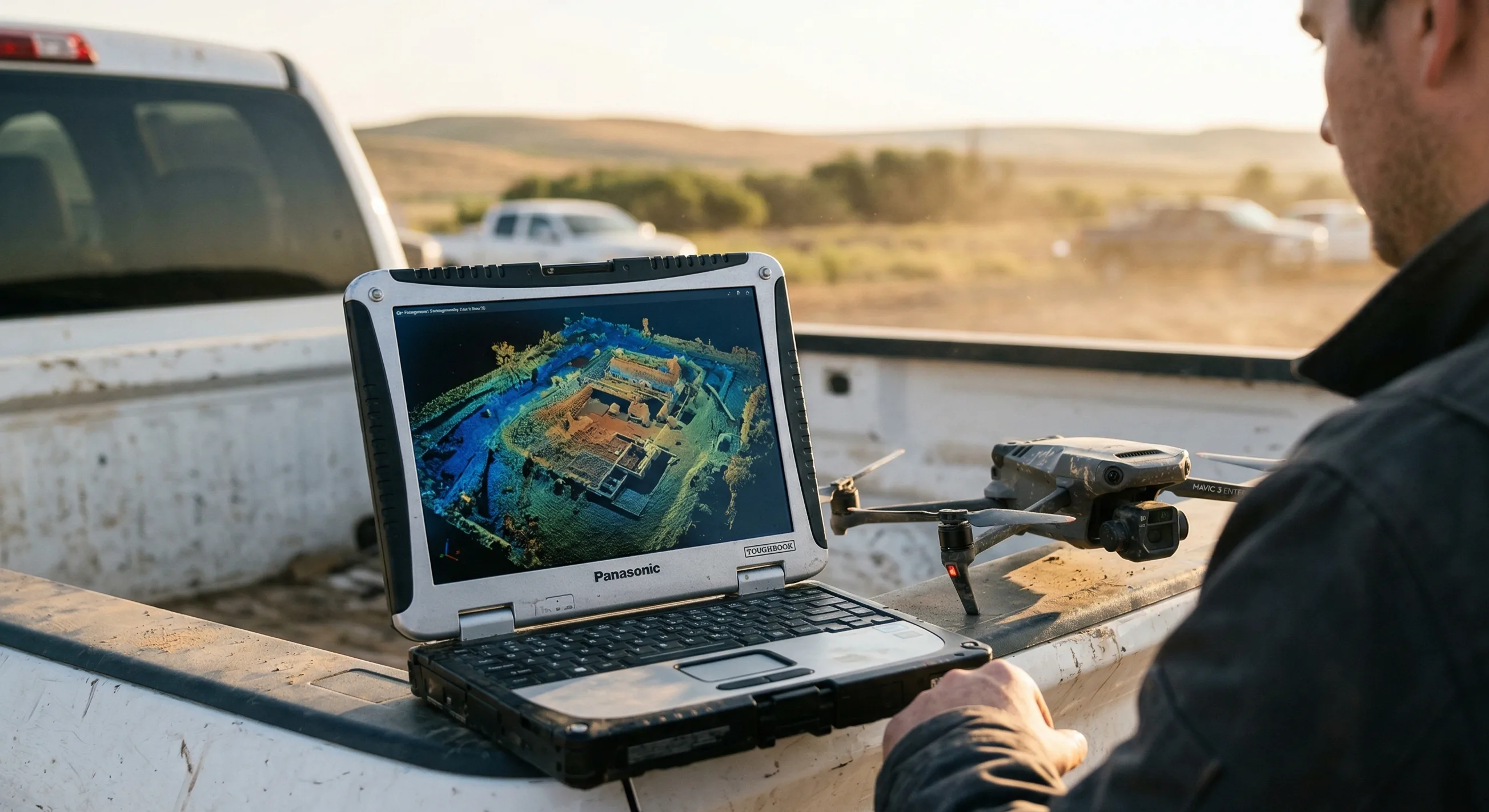
Real-World Scenario: Detailed Mapping Of A Topographical Corridor
Take a 12-mile river corridor planned for flood-plain assessment with a Matrice 350 RTK and Zenmuse P1. A weak plan draws one giant bounding box around the entire corridor and lets the software fill it automatically.
That approach generates hundreds of inefficient cross-corridor lines, wastes power on repeated 180-degree turns, and sends the aircraft over large areas that add no value to the deliverable.
A stronger plan breaks the corridor into overlapping segments, rotates the heading to run with the river, and keeps extra route length beyond each end of the target. The imagery at the ends of each segment then retains enough tie-point support for the Z axis to stay stable instead of collapsing at the edges.
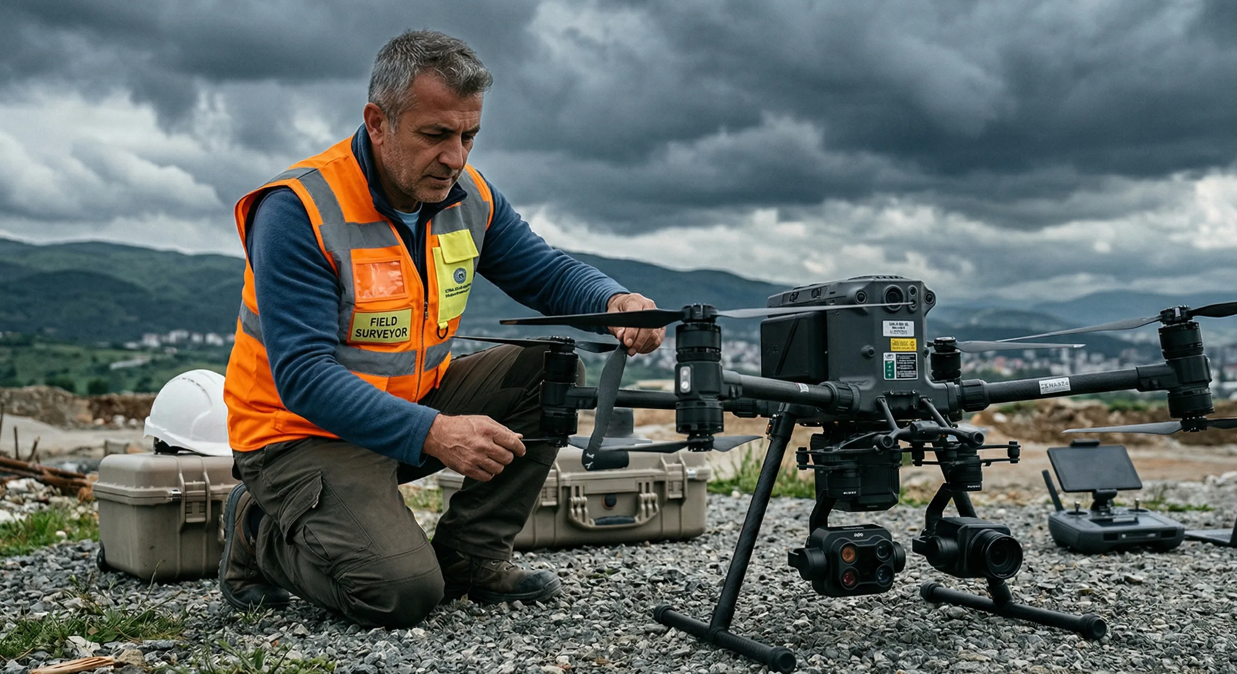
Closing The Loop With Preflight Checks
Even perfect route math can still fail in the field. Battery reserve, launch access, wind, legal restrictions, and rapidly changing light can all make a formally correct plan physically unworkable.
Changing illumination is especially dangerous on mapping jobs. Fast-moving cloud cover can shift the radiometric balance from strip to strip and produce a checkered orthomosaic even when the route itself was geometrically sound.
- Verify that the aircraft can complete the route with realistic battery reserve instead of brochure endurance figures.
- Check whether field hardware remains visible and responsive in direct sun before you rely on it for telemetry.

Field Display
TRIPLTEK 9 PRO Rugged Tablet
The undisputed enterprise standard for field telemetry. Pushes 1,300 sustained nits and refuses to thermal throttle so you never lose visibility in direct midday sun.
- Confirm that current wind and light conditions still support the heading, margin, and overlap you planned.

Wind Meter
BTMETER BT-100 Handheld Anemometer
Wind meters are cheaper than reshoots. Stop guessing crosswinds and log the quantitative data before you launch.
Step-By-Step Workflow: The Preflight Planning Matrix
- Define the exact deliverable and the tolerance it must support before touching route settings.
- Calculate the base GSD, flight height, and sensor choice from that requirement.
- Draw the target polygon and add outward margin so the deliverable sits inside the stronger center of the block.
- Set or override route heading based on terrain orientation, corridor logic, and expected crosswind.
- Audit the environment for lighting, launch space, airspace constraints, and realistic battery demand.
- Do not launch until the route is compatible with both the payload limits and the actual site conditions.
Mission planning is only complete when the route is not just mathematically valid, but safe and repeatable in the real environment.
Use the calculator with this guide
After reading the trade-offs, compare them inside the live calculator so you can see how altitude, overlap, route heading, and camera choice affect the plan on an actual mission footprint.
Related guides
Core Concepts
What Is GSD In Drone Mapping?
Ground sample distance sets the real resolution ceiling for drone mapping. Learn how to calculate it, where low-altitude planning backfires, and how to choose a target that matches the deliverable instead of chasing the smallest possible number.

Overlap & Coverage
Front Overlap Vs Side Overlap
Front overlap and side overlap solve different reconstruction problems. Learn how each one affects alignment stability, strip count, storage growth, and failure risk over low-texture, reflective, or moving surfaces.
Sensor Planning
RGB Vs Thermal Vs Multispectral Planning
RGB, thermal, and multispectral payloads do not share one universal flight recipe. Learn how sensor physics changes altitude, overlap, speed, calibration, and what a useful deliverable looks like for each workflow.